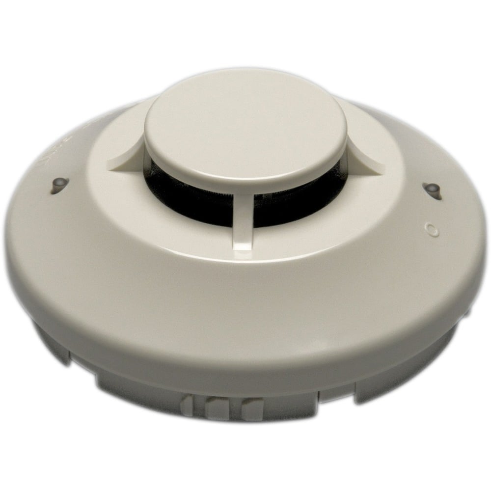
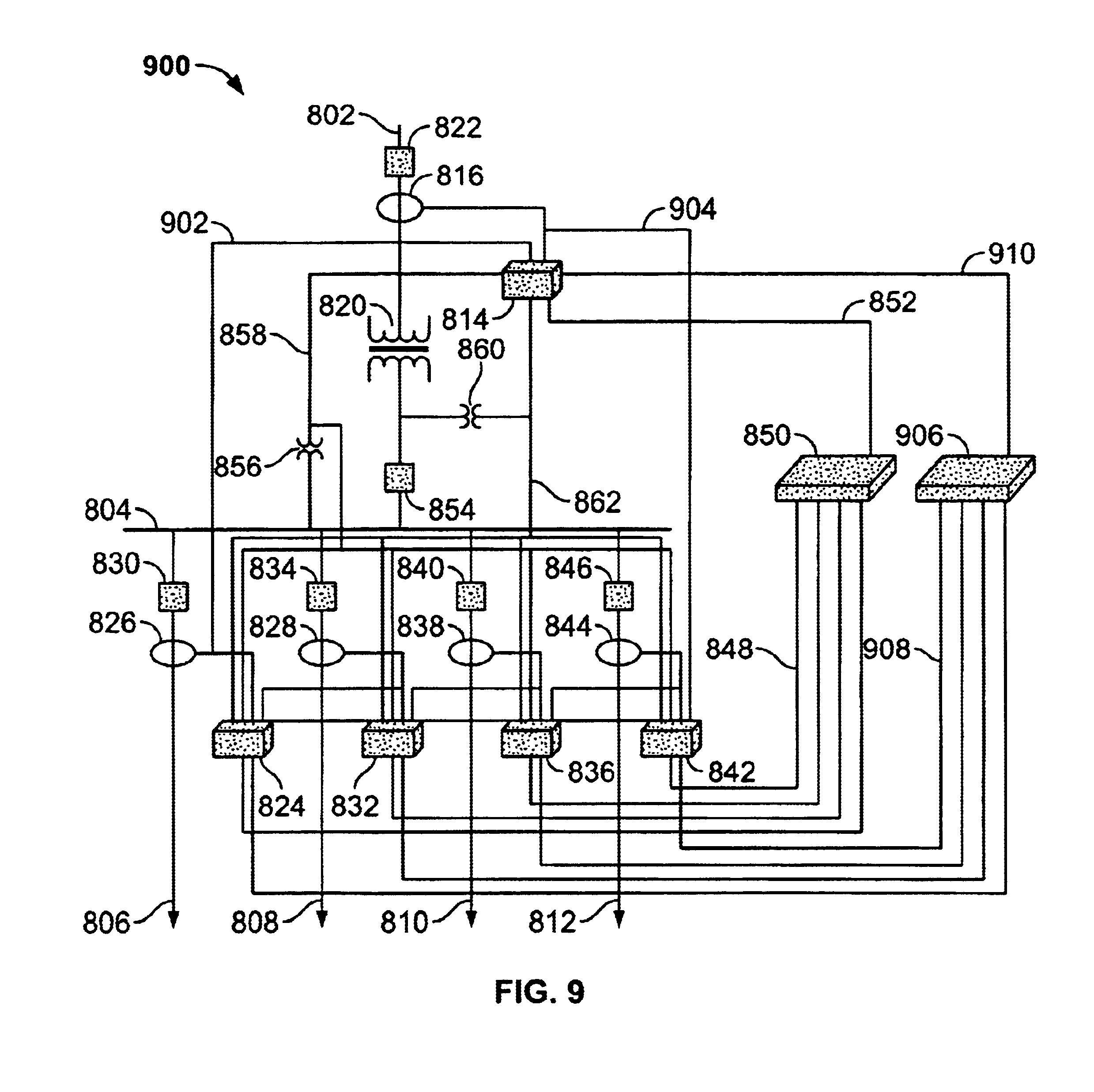
Have you ever walked into a building and immediately smelled smoke, even though you couldn’t see any obvious signs of a fire? This is where duct detectors play a crucial role in fire safety. They are often installed in air-handling systems, like HVAC units, to detect smoke or heat within the ductwork, alerting occupants before a fire spreads. The System Sensor duct detector is a common choice among fire alarm professionals, but understanding its wiring diagram is crucial for proper installation and maintenance.

Image: enginewiringausterlitz.z19.web.core.windows.net
Today, we’ll delve into the world of system sensor duct detector wiring diagrams, exploring the intricacies of these diagrams and how they help us ensure the seamless operation of our fire alarm systems.
Understanding the System Sensor Duct Detector Wiring Diagram
A wiring diagram for a System Sensor duct detector is like a blueprint for electrical connections within the detector. It shows the exact placement of wires, components, and terminals, allowing you to connect everything properly to power up the detector and ensure it works flawlessly. These diagrams are vital for technicians during installation, troubleshooting, and maintenance.
The diagrams can be complex, with different symbols representing various components like the detector itself, its power supply, the alarm control panel, and any supporting circuitry. Understanding these symbols is essential for navigating the diagram correctly and ensuring proper wiring.
Deciphering the Components of a System Sensor Duct Detector Wiring Diagram
Key Elements of a Typical Wiring Diagram
- Detector Terminal Block: This is the point where wires from the duct detector connect to the wiring diagram. Terminals are labeled with letters or numbers, indicating their specific function.
- Power Supply: The power supply provides the necessary voltage (usually 24 volts DC) to operate the detector. It’s important to ensure the correct voltage and polarity are supplied.
- Alarm Control Panel: This is the central hub of the fire alarm system, receiving signals from the detector and initiating appropriate actions like activating alarms or triggering evacuation procedures.
- Auxiliary Relay: Some detectors may have an auxiliary relay, which allows the detector to control external devices, such as exhaust fans or ventilation systems, when a fire is detected.
- Grounding: A grounding wire is essential for electrical safety, ensuring that any stray currents are safely diverted to the earth.

Image: schematron.org
Types of System Sensor Duct Detectors and Their Wiring
System Sensor offers several types of duct detectors, each with specific wiring requirements. The most common types include:
- Ionization Smoke Detectors: These detectors are sensitive to small particles produced by smoldering fires, like those from burning wood or paper.
- Photoelectric Smoke Detectors: These detectors respond to larger particles and are more sensitive to flaming fires, like those from flammable liquids or plastics.
- Heat Detectors: These detectors react to a rise in temperature, typically triggered by a fast-burning fire.
- Combination Smoke and Heat Detectors: These detectors are highly versatile, offering protection against both smoldering and flaming fires.
Each type of detector has a unique wiring configuration, as reflected in its respective diagram. Familiarizing yourself with the specific wiring requirements for your chosen detector is crucial for safe and efficient installation.
Understanding Wire Colors and Functions
While wiring diagrams generally use symbols, colors are also employed to indicate specific wire functions. Red wires typically indicate positive voltage (positive power supply), black wires represent negative voltage (ground), and white or blue wires might be used for relay circuits or alarm signals.
Always check the specific wiring diagram provided by the manufacturer for accurate color assignments.
Tips for Working with System Sensor Duct Detector Wiring Diagrams
Expert Guidance for System Sensor Duct Detector Wiring
- Get the Right Diagram: Always use the specific wiring diagram for the exact model of duct detector you’re working with.
- Double-Check Connections: Always verify that wires are connected to the correct terminals, paying attention to both the color and terminal designation.
- Use Proper Tools: Use only appropriate tools for stripping and connecting wires. Tools like wire strippers and crimp tools are crucial for maintaining electrical safety.
- Grounding is Crucial: Ensure the detector and its associated wiring are properly grounded. This is essential for electrical safety and preventing electrical shocks.
- Test Thoroughly: After completing the installation, always test the detector to ensure it’s working correctly. Conduct a test alarm or a smoke test depending on the specific detector type.
Following these tips can help you minimize wiring errors, ensure a safe and reliable installation, and guarantee optimal performance of your fire alarm system.
FAQs: Common Questions About System Sensor Duct Detector Wiring
Q: What are the different types of wiring diagrams available?
A: There are two main types: schematic diagrams (showing components and connections in a symbolic form) and pictorial diagrams (representing the actual physical layout of the system).
Q: Is it necessary to have a wiring diagram?
A: Absolutely. Wiring diagrams provide a visual guide, preventing mistakes during installation, troubleshooting, and maintenance. They help ensure that everything is connected correctly, minimizing hazards and potential malfunctions.
Q: What should I do if I encounter a wiring problem?
A: If you encounter a wiring issue, immediately shut off power to the detector and consult the wiring diagram. If you’re unsure, contact a qualified electrician or fire alarm technician for assistance.
System Sensor Duct Detector Wiring Diagram
Conclusion
Understanding System Sensor duct detector wiring diagrams is essential for ensuring the functionality of your fire alarm system. These diagrams provide the necessary guidance for proper installation, maintenance, and troubleshooting. Always refer to the specific diagram provided by the manufacturer, double-check connections, and test your detectors regularly to ensure maximum safety.
Are you interested in learning more about fire alarm systems or specific types of detectors? What other topics would you like to explore related to fire safety? Share your thoughts in the comments below!


